Gas-pumping aggregates of GPA C 16. Description of the gas-dynamic sealing system of the GPA-C16 supercharger. Composition of automatic control system
Back in the 1970s, on the basis of the NK-12MA aircraft engine, an installation for GPA-C-6.3 gas pumping unit was created with a capacity of 6300 kW. The creation of this unit was the first experience in the application of an upgraded aircraft engine for the gas supercharger drive. In addition, for the first time, it was practically proved that gas-pumping aggregates of this type can be successfully operated in block containers without a turbocharging shop building, which dramatically reduces the timing of the construction of compressor stations.
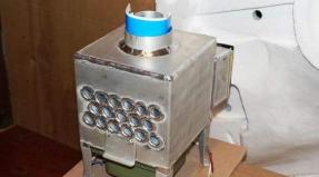
Gipetal aggregates of the GPA-C-6,3 were commissioned at Orenburg-Kuibyshev gas pipelines and "Lower Tura-Perm-Kazan-Gorky" gas pipelines in 1974-1975. For a gas-pumping unit, GPA-C-6.3 was created a special gas turbine installation of the NK-12Te with a free turbine based on this engine with maximum unification of nodes and parts of the serial motor. When creating, a stock of work sustainability was provided with minimal power, quite high efficiency, moderate gas temperature before turbine to guarantee engine reliability. Figure 3.10. Gas pumping unit GPA-C-6.3.
Fig. 3.10. GPA-CO-6,3 gas pumping unit
GPA-C - 6.3 is a block installation consisting of an aviation engine, a centrifugal supercharger of natural gas and auxiliary systems and equipment. All the main elements of the GPA are block modules, joined among themselves at the installation site. Experience in operating the unit confirmed the feasibility of using aircraft engines as a drive of centrifugal gas blowers and the need to improve the design of the unit, its main and auxiliary systems, layout solutions of the COP, as well as a complete block construction of compressor stations with similar aggregates.
The release of the GPA-C-6.3 block and complete unit was the impetus for the adoption of new technical solutions when designing the COP, led to the unification of the master plan for all the projected COPs with these units. Dust collectors, AVO Gas, fuel and starting gas preparation installation and station technological components are designed in block execution. From prefabricated structures, a block of subsidiary services is performed as part of: communication nodes, workshop, boiler room, household premises.

Fig. 3.11. Gas turbine installation of GPA-C-6.3 NK-12T
In fig. 3.11. Gas turbine installation is presented.
Capital costs for the construction of a COP, equipped with GPA-C-6.3 by 35% lower, and construction period is almost 2 times less compared to COP equipped with stationary gas turbines of the same power.
The use of aircraft engine as a GPA drive in block execution was distributed due to a number of advantages overpatient:
High power at low mass;
Rapid installation and dismantling;
Rapid launch and output to mode;
Remote control system and regulating the engine mode;
The possibility of creating mobile gas pumping aggregates;
High technical indicators, etc.
There is experience in using aircraft engines and in the oil industry, for example, on the operation of the PGBU-2 clerk turbochargent installation with the aircraft engine with the Omsk-Tuymase main pipeline system.
(GPa) is fully automated, installed in an individual container and can be operated at ambient temperature from -55 to + 45 ° C.
1.1. Layout aggregate
The unit consists of separate functionally completed blocks and assembly units of full factory readiness, joined each other at the site of operation (Fig. 1 and 2).
Turboboblock with gas turbine engine NK-16St and centrifugal supercharger NTS-16;
- air-reading device (WU);
- the silencer of the suction tract;
- suction chamber;
- intermediate block;
- ventilation unit;
- two blocks of oil coolers;
- exhaust diffuser;
- exhaust mine;
- silencers of the exhaust path;
- automation unit;
- block of oil units;
- fuel gas filters unit;
- system heating of cyclic air;
- fire extinguishing system;
- Container heating system.
The base assembly unit of the unit is a turbob roll installed on a monolithic reinforced concrete foundation. Above the turboblock on a separate support, assembly units of the engine exhaust device and a cyclic air heating system are installed. The air intake for the engine of the NK-16St is carried out through the air-reading device, the noiselessness, the suction chamber and the intermediate block.
In order to ensure the convenience of servicing the unit, the main nodes of the oil system are located in a separate unit of the oil units, and the instruments and shields of the automatic control system of the unit are in the automation unit.
To increase the compactness of the GPa, the blocks of ventilation and oil coolers are placed respectively on the intermediate unit and a block of oil unigs. To increase the reliability of the engine of the NK-16Te, the fuel gas filter block was introduced into the aggregate. The heating of the GPU blocks is carried out by hot air from a nationwide manifold.
The docking of all blocks is performed through flexible adapters, allowing to compensate for the inaccuracy of the installation when installing the unit.
The main designations ................................................ ........ 6.
1. Gau-pumping unit GPA-16 .......................... 9
1.1. Argregate layout ................................................ .........nine
1.2. Unit blocks ................................................ ...............10
1.3. Gas turbine engine NK-16St .................................... 19
1.4. Supercharger NTS-16 ................................................ ........... 23.
2. System of oil delivery of the engine of the NK-16St ............. 29
2.1. Composition of the oil system ................................................. ..thirty
2.2. Operation of the oil system ................................................... ..32.
2.3. The parameters of the system ................................................. 33.
3. System of lubricant supercharger NTS-16 .............................. 35
3.1. Composition of the lubrication system ............................................................. ..... 35.
3.2. Working system ................................................ .............. 35
3.3. Operating parameters of the system .............................................. 38
4. Supercharger sealing system ................................ 39
4.1. Composition of the system ................................................ .............. 39.
4.2. Operation of the seal system ............................................... 39.
4.3. The parameters of the system ................................................. 41.
5. Engine control system NK-16St .................. 42
5.1. Engine start system ............................................... .... 42.
5.1.1. Automatic launch unit ....................................... 42
5.1.2. Air starter ................................................ ..... 45.
5.1.3. Adjusting starter device ................................. 45
5.2. Startup gas supply system ............................. 46
5.3. Fuel gas supply system ........................................... 46
5.4. Hydromechanical engine protection system from
Promotion of the shaft of the power turbine .......................................... 48
5.4.1. Sillar turbine shaft speed limiter .................. 49
5.4.2. Work of hydromechanical protection ................................. 50
5.5. System for regulating the mode of operation ................................. 50
5.5.1. Rollover regulator ................................................ ..... 51.
5.5.2. Gas dispenser .................................................. .............. 52.
5.5.3. Turnover limiter VD .................................... 55
5.5.4. Work system for regulating the mode of operation .................. 56
5.5.5. Management of compressor mechanization elements ............ 58
5.6. System of oil delivery regulation ............................... 60
6. Automatic control system of the GPA-16 gas pumping unit on the basis
MIS MC 4510-39 ............................................ ......................... 61.
6.1. Appointment ............................................................. .................. 61.
6.2. Specifications ............................................. 61
6.3. The main functions performed by the complex MIS 4510
As part of Sau ............................................... .............. 62.
6.3.1. Control functions .................................................. ... 62.
6.3.2. Control functions ............................................... 62
6.3.3. Control functions ................................................ ...... 63.
6.3.4. Information functions ........................................... 63
6.4. The composition of sau ................................................ ..................... 63.
6.5. Structural scheme of the complex ............................................. 64
6.5.1. Control device ............................................... 65
6.5.2. Regulatory device ........................................... 67
6.5.3. The communication device with the object is discrete ........................ 67
6.6. Means of presenting information .................................... 68
6.6.1. The console operator ................................................ ........ 68.
6.6.2. Control Panel................................................ .... 69.
6.7. Software complex "Argus" .......................................... 70
6.7.1. Requirements for hardware and
Software surrounding ........................................... 71
6.7.2. Types of information provided ................................ 71
6.7.3. Organization of the screen ................................................ ... 71.
6.7.4. A generalized alarm window .................................... 72
6.7.5. Terminal................................................. ................ 73.
6.7.6. Terminal windows ................................................ ......... 74.
6.7.7. Alarm window ................................................ .... 74.
6.7.8. Window analog parameters ....................................... 76
6.7.9. The chart window of the analog parameter ............................. 78
6.7.10. The window of the group graphics of analog parameters ............ 79
6.7.11. Window characteristics ................................................ ..80.
6.7.12. The event log................................................ ...... 80.
6.7.13. Retrosystem ................................................... ......... 82.
6.7.14. Control window ................................................ ...... 83.
6.7.15. Window mnemoshem ................................................ .... 84.
6.7.16. Diagnostic window .................................................. .... 85.
6.7.17. The archive window ................................................ .......... 86.
6.7.18. Repair MISS on a working unit ......................... 87
7. The operation of the automatic control system ...... 88
7.1. Preparation of SAU to use ...................................... 88
7.2. The order of working with SAU .............................................. ......... 88.
7.2.1. Work with PEVM ............................................... .......... 88.
7.2.2. Working with the control panel ....................................... 89
7.3. Modes of operation of the GPU ................................................. ........... 89.
7.3.1. Preparation of GPa to start ............................................. 89
7.3.2. Check protection for oil system .................................. 91
7.3.3. Comprehensive check of cranes ....................................... 92
7.3.4. Cold scrolling ................................................ ... 93.
7.3.5. Automatic launch "on the ring" ................................. 93
7.3.6. Exit to "Mainer" ............................................. ... 95.
7.3.7. Transition from "Mainstream" to "Ring" ............................. 96
7.3.8. Normal stop ................................................ ..96.
7.3.9. Emergency Stop................................................ ... 97.
7.3.10. Check emergency protection ........................................ 98
7.3.11. Work of executive mechanisms ............................. 99
7.4. Warning messages and emergency protection GPa ....... 102
7.4.1. Emergency protection emergency protection
With the gas bursting from the contour of the supercharger ................ 102
Back in the 1970s, on the basis of the NK-12MA aircraft engine, an installation for GPA-C-6.3 gas pumping unit was created with a capacity of 6300 kW. The creation of this unit was the first experience in the application of an upgraded aircraft engine for the gas supercharger drive. In addition, for the first time, it was practically proved that gas-pumping aggregates of this type can be successfully operated in block containers without a turbocharging shop building, which dramatically reduces the timing of the construction of compressor stations.
Gipetal aggregates of the GPA-C-6,3 were commissioned at Orenburg-Kuibyshev gas pipelines and "Lower Tura-Perm-Kazan-Gorky" gas pipelines in 1974-1975. For a gas-pumping unit, GPA-C-6.3 was created a special gas turbine installation of the NK-12Te with a free turbine based on this engine with maximum unification of nodes and parts of the serial motor. When creating, a stock of work sustainability was provided with minimal power, quite high efficiency, moderate gas temperature before turbine to guarantee engine reliability. On the fig.3.10. Gas pumping unit GPA-C-6.3.
Fig. 3.10. GPA-CO-6,3 gas pumping unit
GPA-C - 6.3 is a block installation consisting of an aviation engine, a centrifugal supercharger of natural gas and auxiliary systems and equipment. All the main elements of the GPA are block modules, joined among themselves at the installation site. Experience in operating the unit confirmed the feasibility of using aircraft engines as a drive of centrifugal gas blowers and the need to improve the design of the unit, its main and auxiliary systems, layout solutions of the COP, as well as a complete block construction of compressor stations with similar aggregates.
The release of the GPA-C-6.3 block and complete unit was the impetus for the adoption of new technical solutions when designing the COP, led to the unification of the master plan for all the projected COPs with these units. Dust collectors, AVO Gas, fuel and starting gas preparation installation and station technological components are designed in block execution. From prefabricated structures, a block of subsidiary services is performed as part of: communication nodes, workshop, boiler room, household premises.
On the fig. 3.11. Gas turbine installation is presented.
Fig. 3.11. Gas turbine installation of GPA-C-6.3 NK-12T
Capital costs for the construction of a COP, equipped with GPA-C-6.3 by 35% lower, and construction period is almost 2 times less compared to COP equipped with stationary gas turbines of the same power.
The use of aircraft engine as a GPA drive in block execution was distributed due to a number of advantages overpatient:
High power at low mass;
Rapid installation and dismantling;
Rapid launch and output to mode;
Remote control system and regulating the engine mode;
The possibility of creating mobile gas pumping aggregates;
High technical indicators, etc.
There is experience in using aircraft engines and in the oil industry, for example, for the operation of the PGBU-2 turbosate installation with an aircraft engine with the Omsk-Tuymase main pipeline system.
Development of a new generation GPa.
Fig. 3.11. Gas turbine installation of GPA-C-6.3 NK-12T
Fig. 3.10. GPA-CO-6,3 gas pumping unit
GPA-C - 6.3 is a block installation consisting of an aviation engine, a centrifugal supercharger of natural gas and auxiliary systems and equipment. All the basic elements of the GPA are made of self-modules, jammed at the installation site. Experience of the unit confirmed the purpose of the use of aircraft engines as a drive of centrifugal gas pressure and it is extremely important to improve the design of the aggregate of its basic and auxiliary systems, COP layout solutions, as well as a complete block construction of compressor stations with similar aggregates. .
The release of the GPA-TC-6.3 block and complete unit was the impetus for the adoption of new technical solutions in the design of the COP, led to the unification of the master plan for the BDP of the projected COP with these units. Dust collectors, AVO Gas, fuel and starting gas preparation installation and station technological components are designed in block execution. From prefabricated structures, a block of subsidiary services is performed as part of: communication nodes, workshop, boiler room, household premises.
On the fig. 3.11. Gas turbine installation is presented.

Capital costs for the construction of a COP, equipped with GPA-C-6.3 by 35% lower, and construction period is almost 2 times less compared to COP equipped with stationary gas turbines of the same power.
The use of aircraft engines as a GPA actuator in block execution was distributed due to a number of advantages overpatient:
High power at low mass;
Rapid installation and dismantling;
Rapid launch and output to mode;
Remote control system and regulating the engine mode;
The possibility of creating mobile gas pumping aggregates;
High technical indicators, etc.
There is experience in using aviation engine and in the oil industry, for example, the operation of the PGBU-2 turbo-pump installation with aviation engine with the system of the Omsk-Tuymase main pipeline system.
The GPA gas turbine park includes more than 20 types of aggregates (about 3000pcs) by a single power of 0.5 to 25 MW, with nominal kp.d. from 23 to 34%. Most of this fleet morally and physically outdated and requires replacement, because In 46% of the exhibition aggregates is 50-100 thousand.
The huge park of stationary GPA type of GTK-10-4 and GTN-16 should not be updated:
Due to the lack of necessary huge financial resources for the purchase of material part;
The period of the economy of the Russian economy led to the fall of production and personnel potential;
The proposed new generation GPa must undergo pillar operation to confirm the technical and economic indicators in conditions of long-term operation and determine the costs of implementing and the needs of repair and maintenance.
Evaluating the state of the aggregates of GTK-10-4 and GTN-16 operating at present, it is possible to conclude that these aggregates have not yet used their entire potential, and the modernization of individual nodes will increase the technical level and the competitiveness of these aggregates at significantly lower costs and will provide Fork-indirect update of the GPa Park.
The main technical directions of the modernization of GTK-10-4 in order to improve the passport values \u200b\u200bof the power and kp. are:
Regenerator replacement for a lamellar type to more reliable, for example, tubular;
Reducing the radial gaps of turbomachine;
The introduction of combined two-channel burners with preliminary mixing of the fuel-air mixture to reduce the concentration of NO X and CO.
Integrated implementation of measures for the modernization of GTK-10-4 will increase the power of the unit and bring to KPD. GTU up to 30.5%.
One of the possible ways to increase kp. GTU GTN-16 is its transfer to the regenerative cycle, which gives an increase in KPD with a regeneration 0.85. Cycle up to 35%. At the same time, such modernization will require significant changes in the design of GTU. First of all, this concerns the hull of the turbine, its strength and stiffness in the zones of attachment of pipes of removal and flow of cyclical air into the regenerator and after it to the combustion chamber. A difficult task is also a layout of such a GTU in disharmed accommodation in shelter. Requires redeployment and high pressure turbines (LDD) and low pressure turbines (TND). For the combustion chamber, it is necessary to generate new burner devices and adjusting the automatic control system (SAR). These changes to transfer the installation to the regenerative cycle in terms of financial costs are comparable to the development or replacement of a new generation GTU. Such units include the GPU developed in recent years on the basis of conversion potential: GPA-16''Fu''' (Umpo), GPa-12''URAL'''' with the drive of PS-90A; GPa-16''URAL''' (NGO''isra''''') and others.
Posted on Ref.rf
.
To ensure reliability of serial products, their phased implementation is produced. After the bench tests of one-two (or more), the first samples of the drive samples are installed for acceptance tests and the accumulation of proactive developments in the operated unit on the pilot-industrial COP. At the same time, a head pattern of a complete GPa is manufactured and tested. According to the results of the acceptance tests, a decision is made to produce an experienced (installation) party from three-five aggregates. The decision on mass production is made on the basis of a set of tests and experimental and industrial operation.
A similar approach to a new generation GPa has a number of advantages:
The structure of the structure to modernization is based on the sizes of the superchalar with minimal costs in different versions (replacement of the drive, installation on existing foundations in the operated shops or individual buildings, replacing the block and container GPA on the existing site, etc.);
Full factory readiness in block execution;
Elevated kpd GTU up to 37%;
Unification of drives and gas compressors, ensuring their use in various combinations, as well as unification with units for power plants;
Staffing with a waste disposal for heat supply;
High reliability (20-25 thousand. Used - Middle Repair, 40-50 thousand. - Overhaul);
Economy;
Malaya metal;
Improving the working conditions of the service personnel;
Automation of production processes;
Improved environmental characteristics, i.e. reduction of emissions of harmful substances.
The experience of operating the COP does not give an unequivocal response about the comparative advantages of aviation or stationary industrial type GTU. Aviation drives, having a higher fuel efficiency, require for repair and maintenance 2-2.5 times more costs. In this case, a centrifugal compressor machine remains the basic type of gas compressor.
The main successes of recent years to improve existing structures are associated with the creation of a number of unified structures with a different number of working wheels; Developing and implementing a variety of modernization projects operated by the injection, incl. and with increasing power; Creation of''Shih'''''''s oil-free seals; Mass introduction of highly efficient anti-accomplicity systems; Increase the resource and interservice maintenance of GTU.
Today, work is actively under the replacement of obsolete gas pumping units of the State Code of GTK-10-4, GTN-25 to the aggregates of the new generation of GPA-12 (16) R''URAL'', GPa-25R''URAL''', GPa-16R''Ufa''' 'with Aviation motors of Perm and Ufa production.
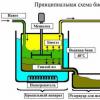
 Fig. 3.12. Scheme of gas pumping unit GPa-16R''Ufa''''''''''''''''''''''''''''''''''''''''''''''''''''''
1 - Quow; 2 - the absorption path from the Quow to the receiving chamber; 3 - a reception chamber; 4 - input device; 5 - engine al-31st; 6 - gas feed (snail removal of exhaust gases); 7 - protective casing; 8 - tract exhaust; 9 - heat excavator; 10 - exhaust pipe; 11 - coupling; 12 - supercharger with a replaceable running part; 13 - the sealing air supply system into the butt portion of the supercharger; 14 - engine avo; 15 - car supercharger; 16 - engine cooling system; 17 - Block-box SAU GPA; 18 - supercharger lubrication system; 19 - engine lubrication system; 20 - transition frame on supporting structures; 21 - a system of flushing a gas-air path; 22 - Fuel Gas Proprietary System.
 Fig. 3.13. Gas turbine drive AL-31STN production of PJSC (until 2015 OJSC)''Umpo'''''''''
The introduction of a new generation engine made it possible to reduce the consumption of fuel gas almost twice, which contributed to the improvement of the ecological situation, ᴛ.ᴇ. Reducing emissions of harmful substances into the atmosphere (NO x - 110mg / m 3, CO - 50 mg / m 3), which corresponds to the best global achievements in the field of gas transport.
The automation system installed on the new GPa allows you to carry out control, regulating and informational functions: automatic readiness checking for starting, automatic launch of the GPA with loading or without loading the unit in the track, automatic stabilization of a given mode of operation of the GPA when protecting protection, antippagry control and antipoplated supercharger protection, Remote control of individual GPA mechanisms, emergency stop at the operator's team, phased start, automatic and remote control of the fire protection system. There is a signaling of communication line, gas leakage, voltage disappearance, autopsy automation.
The use of GPA from different manufacturers with drives of different types allows you to most unify and ensure interchangeability, increase the manufacturability of repairs and further reduced costs, incl. on modernization.
The Al-31st engine (Umpo) differs from PS-90GP (PJSC (until 2015)''Aviad Moon) not only constructively: Perm (PS-90GP) is a two-way, and Ufa (AL-31ST) has a more complex tricks of the rotors. Al-31st is more powerful and more economical PS-90GP, but loses while ecology (NO x emissions), noise and heat generation.
Along with the reconstruction of the GPU workshops, the reconstruction of intercity communications, pumping oils, an emergency diesel power plant, compressor compressed air, gas preparation installation, gipstorm and other systems.

 .
.
Development of a new generation GPa. - Concept and species. Classification and features of the category "Development of a new generation GPa." 2017, 2018.
Gas turbine aggregates, as noted above, are divided into: stationary, aviation and ship.
To stationary gas turbine installations, specifically designed for use on gas pipelines, include installation: GT-700-5, GTK-5, GT-750-6 GT-6-750, GTN-6, GTK-10-2-4, GTN -25 with a capacity of 4 MW to 25 MW;
Aviation gas turbine plants include a GPA, where the supercharger drive is the gas turbine of the aviation type, specially reconstructed for use on trunk gas pipelines. Currently, gas pipelines are operated on gas pipelines such as GPA-TS-6.3, GPA-TC-6.3 / 76 and GPA C-6.3 / 125 with the NK-12Te engine, manufactured by Samara Motor-Building Association and Sumy Machine Building Association. The Sumy Machine-Building Association is assembling an aggregate of the GPA-C-16 type with the engine of the NK-16St.
The aircraft aggregates include the installation of imported production type "Cober -182" with the engine of Avon 1534-1016 of Roll-Royce (United Kingdom) and Zavtavr firms "Solar" (USA).
The shipping gas turbine aggregates include the installation of the type GPU-10 "Wave" with the engine of DR-59l, manufactured by the Nikolaev shipbuilding plant and DT-90 (Ukraine).
In total, over 3 thousand GTU of various types and schemes with a total installed capacity of over 36 million kW were operated on gas pipelines at the end of 2001, which is about 85% of the total installed capacity of Gazprom compressor stations.
Passport characteristics and the number of gas turbine installations of various types used currently on gas pipelines are characterized by data Table. 5.1.
Table 5.1.
Types of gas turbine installations used on gas pipelines
| Type GTU | Efficiency,% | Single power, kW | Number of GPa, pieces | Total power, kW |
| Centaur GT-700-5 GTK-5 GT-750-6 GT-6-750 GTN-6 GPA-C - 6.3 GTK-10 GTC-10I GPU-10 GTRR-10 J-59 Koberra-182 GTRR-12 , 5 GTK-16 gTN-16 GPa-C-16 GPU-16 / GPa-16 DG-90 GTN-25 GPA-TC-25 GTK-25 | 2620/3900 6000/6500 11900/12900 | 20/10 99/5 19/14 58/19 | ||
| TOTAL | - | - |
Data analysis Table. 5.1 shows that a number of power GTU used on the main gas pipelines of Gazprom varies in the range from 2 to 25 MW. The passport efficiency used by the aggregates varies in the range of 24-35%, and the numerical value of the aggregate efficiency is usually increasing with its increasing power.
Analysis of the experience of using gas turbine installations on trunk gas pipelines shows that during the development and development of a unified gas supply system (ESG) of Russia, over twenty different types of this type of centrifugal blowers drive, made by various gas turbine manufacturers, which involuntarily led to mismatch In technological, thermodynamic and gas-dynamic indicators of the installers used.
In particular, it led to the fact that among the exploited gas-pumping units of various capacities created in the period of the 70-80 years, the speed of rotation of the shaft "Power turbine - centrifugal supercharger" varies in the range of 3700-8200 rpm., There is no single approach to justification The numbers of steps in power turbines and centrifugal superchargers are based on, for example, from their loading.
It all testifies to a certain extent that at present Gazprom OJSC in the transition from metal-efficient technology, which took place in the initial period of the creation of the ESG, to the energy-saving, does not have a "its" - the main type of gas turbine powerport, fully responded The requirements of the energy-saving gas transport technology. In one time, the largest distribution on gas pipelines, the aggregate of the GTK-10 type currently requires reconstruction, at least in part of the rationale for the use of the parameters of the regenerative cycle of the installation and the assessment of the use on gas pipelines of such aggregates as a whole.
The desire of the operational staff of the COP to reduce energy costs for the needs of gas pumping, lead in a number of cases to the modernization and reconstruction of already established aggregates in order to improve their economic indicators. This is primarily a translation of the GTN-25 and GTN-10 type of the type of GTN-25 and GTN-10, the creation of installations of the "BUCE" type steps-c-6,3, and the like.
In recent years, the development of gas-saving gas technology during gas pipelines in gas pipelines reiterates attention to the rationale for the use of regenerative GTU on gas pipelines, comparison without regenerative and regenerative units, the possibilities of use and other heat engineering activities that contribute to the reduction of gas pipelines in gas pipelines.
Each of these types of drives of compressor stations has their advantages and disadvantages, potential opportunities and restrictions on further development.
The essential advantages of the GPU with a gas turbine type of actuator should be attributed primarily a high specific power per unit of mass, the ability to regulate the supply of technological gas due to the change in the speed of rotation of the power turbine of GTU, the possibility of using the pumped gas as fuel, relatively small water consumption and oil is relatively small, for example With piston internal combustion engines, direct rotational movement and complete balance, which eliminates the need to use powerful foundations, the real possibilities for further improvement of the main indicators of GTU and, above all, its efficiency.
The disadvantages of most exploited gas turbine installations on gas pipelines should include relatively low effective efficiency and high noise levels, especially in the area of \u200b\u200bthe air intake chamber GTU. It should be noted that the gas turbine installation on gas pipelines must be considered as an aggregate that practically produces two types of energy: mechanical on the shaft of the supercharger and heat in the form of heat of exhaust gases, which can and should be used to effectively use for the heating of office spaces of the COP in the autumn-winter period of their operation And for other reference purposes.
Currently, the manufacturers of the GPU with a gas turbine drive are mastering the production of gas turbines of a new generation with a capacity of 6-25 MW with efficiency at 32-36%. To such aggregates, first of all include the GPA type of GTN-25-1, GPa-C-6.3 with the NK-14 engine, GPA-C-16 with Motors AL-31, NK-38ST, etc. (Table 5.2 ).
Table 5.2.
Indicators of promising gas turbine plants of the new generation
| Mark GPa | Engine brand | engine's type | Power, MW. | Efficiency,% | TE-RA before TVD, 0 C | The degree of compression in the cycle |
| GPa-2.5 GPU-6 GPa-Ts-6,3A GTN-6U GPA-TC-6,3B GPU-10A GPA-12 Ural GPA-C-16S GPA-C-16L GPA-TC-16A GTRRR -16 GTN-25-1 GPa-C-25 GPU-25 | GTG-2.5 DT-71 D-336 GTN-6U NK-14US DN-70 PS-90 DG-90 Al-31st NK-38St - - NK-36T-80 | Ship ship police station. Avia Ship Avia Ship Avia Air Station. Station. Air ship | 2,5 6,3 6,3 6,3 8,0 10,0 12,0 16,0 16,0 16,0 16,0 25,0 25,0 25,0 | 30,5 30,0 30,5 30,0 35,0 34,0 34,0 33,7 36,8 33,0 31,0 34,5 35,0 | 13,0 13,4 15,9 12,0 10,5 17,0 15,8 18,8 18,1 25,9 7,0 13,0 23,1 21,8 |
Consideration of data Table. 5.2 shows that in the near future, stationary, ship and aviation units will remain the main types of gas turbine energy receipt on gas pipelines, and the latter will be used in a larger and more.