It's called a surface outline. Examples of constructing outlines of projections of a body of revolution with an inclined axis. An example of constructing an outline of a surface of revolution
Surface concept
SURFACES
In descriptive geometry, surfaces are considered as a set of successive positions of a certain line moving in space according to a certain law. This way of forming a surface is called kinematic.
A line (curve or straight line) moves in space according to a certain law and creates a surface. It is called generator. During the formation of the surface, it can remain unchanged or change its shape. The law of movement of the generatrix is given in the form of a set of lines and indications of the nature of the movement of the generatrix. These lines are called guide lines.
In addition to the kinematic method, the surface can be defined
Analytically, i.e., described by a mathematical expression;
wireframe method, which is used when defining complex surfaces; surface skeleton is an ordered set of points or lines belonging to the surface.
To define a surface on a complex drawing, it is enough to have such surface elements on it that allow you to build each of its points. The combination of these elements is called the surface determinant.
The surface determinant consists of two parts:
· geometric part, including permanent geometric elements (points, lines) that participate in the formation of the surface;
· the algorithmic part that defines the law of motion of the generatrix, the nature of the change in its shape.
In symbolic form, the determinant of the surface F can be written as: F(Г)[A], where Г is the geometric part of the determinant, А is the algorithmic part.
In order to isolate the determinant near the surface, one should proceed from the kinematic method of its formation. But since many identical surfaces can be obtained in different ways, they will have different determinants. Below we will consider the most common surfaces in accordance with the classification criteria adopted in the course of descriptive geometry.
To specify a surface on a complex drawing, it is enough to specify the projections not of the entire set of points and lines belonging to the surface, but only of the geometric shapes that are part of its determinant. This way of specifying the surface allows you to build projections of any of its points. Defining a surface by projections of its determinant does not provide clarity, which makes it difficult to read the drawing. To improve clarity, if possible, sketch lines (sketches) of the surface are indicated on the drawing.
When some surface W is projected parallel to the projection plane S, then the projecting lines tangent to the surface W , form a cylindrical surface (Fig. 11.1). These projected lines touch the surface W at points forming a certain line m, which is called a contour line.
The projection of the contour line m on the plane S - m / , is called the outline of the surface. The outline of the surface separates the projection of the surface from the rest of the projection plane.
The surface contour line is used in determining the visibility of points relative to the projection plane. So, in fig. 11.1 projections of points of the surface W, located to the left of the contour m, on the plane S will be visible. The projections of other points on the surface will be invisible.
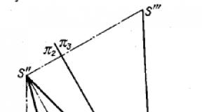
On fig. 354 shows a straight circular cone, the axis of which is parallel to the square. π 2 and inclined to the square. π 1 The outline of its frontal projection is given: it is an isosceles triangle S"D"E". It is required to construct an outline of the horizontal projection.
The desired outline is made up of a part of an ellipse and two straight lines tangent to it. Indeed, the cone in its given position is projected onto the square. π 1 using the surface of an elliptical cylinder, the generators of which pass through the points of the circumference of the base of the cone, and using two planes tangent to the surface of the cone.
An ellipse on a horizontal projection can be built along its two axes: a small D "E" and a large one, equal in size to D "E" (the diameter of the circumference of the base of the cone). The lines S "B" and S "F" are obtained by drawing tangents to the ellipse from the point S ". The construction of these lines consists in finding the projections of those generators of the cone along which the cone and the planes mentioned above come into contact. For this, a sphere inscribed in cone Since the plane projecting onto π 1 simultaneously touches the cone and the sphere, it is possible to draw a tangent from the point S "to the circle - the projection of the equator of the sphere - and take this tangent as the projection of the desired generatrix. The construction can be started by finding point A "- the frontal projection of one of the points of the desired generatrix. Point A" is obtained at the intersection of the frontal projections: 1) the circle of contact between the cone and the sphere (line M "N") and 2) the equator of the sphere (line K "L "). Now you can find the projection A "on the horizontal projection of the equator and through the points S" and A "draw a line - the horizontal projection of the desired generatrix. Point B is also determined on this line, the horizontal projection of which (point B") is the point of contact of the line with the ellipse.
With the construction of outlines of the projections of the cone of revolution, we meet, for example, in this case: given the projections of the top of the cone (S", S "), the direction of its axis (SK), the dimensions of the height and diameter of the base; construct projections of the cone. On fig. 355 this is done using additional projection planes.
So, to build a frontal projection, sq. π 3 perpendicular to π 2 and parallel to the straight line SK, which determines the direction of the cone axis. On the projection S""K"" the segment S""C"" is plotted, equal to the given height of the cone. At point C"" a perpendicular to S""C"" is drawn, and a segment C""B"" is drawn on it, equal to the radius of the base of the cone. By points C"" and B"" the points C" and B" are obtained, and thus the minor semi-axis C"B" of the ellipse-frontal projection of the base of the cone is obtained. The segment C"A" equal to C""B"" represents the semi-major axis of this ellipse. Having the axes of the ellipse, it is possible to construct it as shown in Fig. 147.

To construct a horizontal projection, the projection plane π 4 is introduced, which is perpendicular to π 1 and parallel to SK. The construction progress is similar to that described for the frontal projection.
How to build projection sketches? On fig. 356 shows a different one than in fig. 354, the method of drawing a tangent to an ellipse - without a sphere inscribed in a cone.
First, with a radius equal to the minor semiaxis of the ellipse, an arc was drawn from its center (in Fig. 356 this is a quarter of a circle). The point 2 of the intersection of this arc with a circle of diameter S"C" is determined. A straight line is drawn from point 2 parallel to the major axis of the ellipse; this

the line intersects the ellipse at points K "1 and K 2. Now it remains to draw straight lines S "K" 1 and S "K" 2, they are tangent to the ellipse and are included in the outline of the frontal projection of the cone.
On fig. 357 shows a body of revolution with an inclined axis parallel to the square. π 2. This body is bounded by a combined surface consisting of two cylinders, the surface of a circular ring and two planes. The sketch of the frontal projection of this body is its main meridian.
The outline of the horizontal projection of the upper cylindrical part of a given body is made up of an ellipse and two straight lines tangent to it. The straight line A"B" is a horizontal projection of the generatrix of the cylinder, along which the plane projecting onto π 1 touches the surface of the cylinder. The same applies to the sketch of the projection of the lower cylinder (in Fig. 357 this sketch is not shown in full).
Let's move on to the more difficult part of the essay - the intermediate one. We must construct a horizontal projection of that spatial curve line, at the points of which the projecting lines pass, tangent to the surface of the circular ring and perpendicular to the square. pi 1 . The frontal projection of each point of such a curve is constructed in the same way as was done for point A "in Fig. 354, using inscribed spheres. The horizontal projections of the points are determined on the projection of the equator of the corresponding sphere. For example, point D 1 (D" 1 , D" 1).
Points K "1 and K" 2 are obtained from the point K "1 (aka K" 2) on the equator of the sphere with center O, and this point K "1 (K" 2) is obtained by drawing a communication line tangent to the constructed curve B "D" 1 C".
So, the curve B"D" 1 K" 1 contains frontal projections of points whose horizontal projections B", D" 1 , K" 1 are included in the outline of the horizontal projection of the body under consideration.
Questions to §§ 53-54
- What is called a plane tangent to a curved surface at a given point on this surface?
- What is called an ordinary (or regular) point on a surface?
- How to construct a plane tangent to a curved surface at some point on it?
- What is the surface normal?
- How to construct a plane tangent to the sphere at some point on the sphere?
- When is a curved surface classified as convex?
- Can a plane tangent to a curved surface at any point on that surface intersect the latter? Give an example of an intersection along two lines.
- How are spheres inscribed in a surface of revolution, the axis of which is parallel to the square, used? π 2 , to construct an outline of the projection of this surface on the square. π 1 with respect to which the axis of the surface of revolution is inclined at an acute angle?
- How to draw a tangent to an ellipse from a point lying on the continuation of its minor axis?
- In what case will the outlines of the projections of the cylinder of revolution and the cone of revolution be exactly the same on the square. π 1 , and pl. p2?
On fig. 354 shows a straight circular cone, the axis of which is parallel to the square. π 2 and inclined to the square. π 1 The outline of its frontal projection is given: it is an isosceles triangle S"D"E". It is required to construct an outline of the horizontal projection.
The desired outline is made up of a part of an ellipse and two straight lines tangent to it. Indeed, the cone in its given position is projected onto the square. π 1 using the surface of an elliptical cylinder, the generators of which pass through the points of the circumference of the base of the cone, and using two planes tangent to the surface of the cone.
An ellipse on a horizontal projection can be built along its two axes: a small D "E" and a large one, equal in size to D "E" (the diameter of the circumference of the base of the cone). The lines S "B" and S "F" are obtained by drawing tangents to the ellipse from the point S ". The construction of these lines consists in finding the projections of those generators of the cone along which the cone and the planes mentioned above come into contact. For this, a sphere inscribed in cone Since the plane projecting onto π 1 simultaneously touches the cone and the sphere, it is possible to draw a tangent from the point S "to the circle - the projection of the equator of the sphere - and take this tangent as the projection of the desired generatrix. The construction can be started by finding point A "- the frontal projection of one of the points of the desired generatrix. Point A" is obtained at the intersection of the frontal projections: 1) the circle of contact between the cone and the sphere (line M "N") and 2) the equator of the sphere (line K "L "). Now you can find the projection A "on the horizontal projection of the equator and through the points S" and A "draw a line - the horizontal projection of the desired generatrix. Point B is also determined on this line, the horizontal projection of which (point B") is the point of contact of the line with the ellipse.
With the construction of outlines of the projections of the cone of revolution, we meet, for example, in this case: given the projections of the top of the cone (S", S "), the direction of its axis (SK), the dimensions of the height and diameter of the base; construct projections of the cone. On fig. 355 this is done using additional projection planes.
So, to build a frontal projection, sq. π 3 perpendicular to π 2 and parallel to the straight line SK, which determines the direction of the cone axis. On the projection S""K"" the segment S""C"" is plotted, equal to the given height of the cone. At point C"" a perpendicular to S""C"" is drawn, and a segment C""B"" is drawn on it, equal to the radius of the base of the cone. By points C"" and B"" the points C" and B" are obtained, and thus the minor semi-axis C"B" of the ellipse-frontal projection of the base of the cone is obtained. The segment C"A" equal to C""B"" represents the semi-major axis of this ellipse. Having the axes of the ellipse, it is possible to construct it as shown in Fig. 147.
To construct a horizontal projection, the projection plane π 4 is introduced, which is perpendicular to π 1 and parallel to SK. The construction progress is similar to that described for the frontal projection.
How to build projection sketches? On fig. 356 shows a different one than in fig. 354, the method of drawing a tangent to an ellipse - without a sphere inscribed in a cone.
First, with a radius equal to the minor semiaxis of the ellipse, an arc was drawn from its center (in Fig. 356 this is a quarter of a circle). The point 2 of the intersection of this arc with a circle of diameter S"C" is determined. A straight line is drawn from point 2 parallel to the major axis of the ellipse; this
the line intersects the ellipse at points K "1 and K 2. Now it remains to draw straight lines S "K" 1 and S "K" 2, they are tangent to the ellipse and are included in the outline of the frontal projection of the cone.
On fig. 357 shows a body of revolution with an inclined axis parallel to the square. π 2. This body is bounded by a combined surface consisting of two cylinders, the surface of a circular ring and two planes. The sketch of the frontal projection of this body is its main meridian.
The outline of the horizontal projection of the upper cylindrical part of a given body is made up of an ellipse and two straight lines tangent to it. The straight line A"B" is a horizontal projection of the generatrix of the cylinder, along which the plane projecting onto π 1 touches the surface of the cylinder. The same applies to the sketch of the projection of the lower cylinder (in Fig. 357 this sketch is not shown in full).
Let's move on to the more difficult part of the essay - the intermediate one. We must construct a horizontal projection of that spatial curve line, at the points of which the projecting lines pass, tangent to the surface of the circular ring and perpendicular to the square. pi 1 . The frontal projection of each point of such a curve is constructed in the same way as was done for point A "in Fig. 354, using inscribed spheres. The horizontal projections of the points are determined on the projection of the equator of the corresponding sphere. For example, point D 1 (D" 1 , D" 1).
Points K "1 and K" 2 are obtained from the point K "1 (aka K" 2) on the equator of the sphere with center O, and this point K "1 (K" 2) is obtained by drawing a communication line tangent to the constructed curve B "D" 1 C".
So, the curve B"D" 1 K" 1 contains frontal projections of points whose horizontal projections B", D" 1 , K" 1 are included in the outline of the horizontal projection of the body under consideration.
Questions to §§ 53-54
- What is called a plane tangent to a curved surface at a given point on this surface?
- What is called an ordinary (or regular) point on a surface?
- How to construct a plane tangent to a curved surface at some point on it?
- What is the surface normal?
- How to construct a plane tangent to the sphere at some point on the sphere?
- When is a curved surface classified as convex?
- Can a plane tangent to a curved surface at any point on that surface intersect the latter? Give an example of an intersection along two lines.
- How are spheres inscribed in a surface of revolution, the axis of which is parallel to the square, used? π 2 , to construct an outline of the projection of this surface on the square. π 1 with respect to which the axis of the surface of revolution is inclined at an acute angle?
- How to draw a tangent to an ellipse from a point lying on the continuation of its minor axis?
- In what case will the outlines of the projections of the cylinder of revolution and the cone of revolution be exactly the same on the square. π 1 , and pl. p2?
Rice. 7.2. Construction of projections of surfaces: a- cylindrical; b– spheres
essay surfaces are called the line that limits the projection of the figure on the plane of projections. The projections of any point on the surface lie inside the outline (in a particular case, on the outline). If the line of the surface contour is the generatrix of the surface, then it is called contour generatrix, and its projection sketch generatrix.
When constructing a surface diagram, the projection direction coincides with the direction of the observer’s gaze, therefore the contour line is the boundary of the surface visibility: that part of it that is located in front of the contour line is visible, the rest is invisible.
The sketch line divides the projection into visible and invisible parts. The projections of the surface points located on the sketches will be called change points (boundaries) of visibility. Invisible points are usually denoted in brackets.
7.3. Surface classification
The variety of surface shapes creates great difficulties in their study. In order to ensure the process of studying surfaces, it is necessary to systematize them. Unfortunately, it is not possible to develop a universal classification of surfaces. Within each method of surface formation there is its own basis for systematization, for example, in the kinematic method of surface formation, systematization is based on the type of generatrix and the law of its displacement. One of the possible classifications is shown in Fig. 7.3.

Rice. 7.3. Surface classification
Ruled surfaces.Surfaces that are formed during some regular movement of a straight line in space are called ruled.Ruled surfaces are generally uniquely defined by three guide lines m, n, f.
Ruled surfaces are divided into developing and non-developing. deployable surfaces can be combined with the plane without deformation (folds and breaks). The most common developable surfaces are: cylindrical, conical, with a return rib (torso), prismatic, pyramidal.
Surfaces of revolution of a general form. Surfaces of revolution of a general form are surfaces formed by an arbitrary line (generating l) during its rotation around a fixed axis (surface axis i).
When specifying a surface of revolution on a complex drawing, the axis of rotation i is placed perpendicular to one of the projection planes. Surface elements: m- prime meridian 1
- throat, 2
- equator
(Fig. 7.4, a). In this case, all parallels of the surface, throat 1
and equator 2
are projected onto P 1 in the true value, and onto P 2 - into line segments perpendicular to i 2 are projections of the i axis. To set the surface of revolution of a general view on a complex drawing, projections of the main meridian are built m 1 and m2, carry out projections of the throat, equator and two parallels (7.5, b).
Properties of surfaces of revolution.
1. Rotating around its axis, the surface can move without deformation along itself.
2. If the meridian of the surface of revolution passes through two points of the surface, then it is the shortest line between these points and all meridians are equal to each other.
3. Each of the parallels of the surface of revolution intersects the meridian at a right angle, i.e., the parallels and meridians form a rectangular network on the surface of revolution.
4. The surface of revolution can be defined as a curve if this curve intersects all the moves of the points of the generatrix.
Ruled developable surfaces of revolution. Ruled developable surfaces of revolution are surfaces formed by the rotation of a rectilinear generatrix l around the fixed axis of the surface I along a curved or broken guide m, the development of which can be combined with a plane without breaks and folds.
The most common ruled developable surfaces of revolution are: a cylinder of revolution, a cone of revolution, a one-sheeted hyperboloid (Table 7.1).